Endeavour into Automation
My journey to become an automation engineer.
Project maintained by tkaden4
Posts
- Making a PLC Training Board, Pt. 1
- Tinning and splicing wires together
- DC part 1: Series Resistances
- About + Introduction
DC part 1: Series Resistances
October 08, 2020
This post is the first in a series dedicated to basic electronics and lab work assigned to me during my classes. These posts will be interspersed with original content, so most weeks there will be 2 posts, one for labs and one for an original project of my own design. While the content is aimed at beginners to electronics, I’ll be attempting to be as concise as possible and not over-explain.
Lab Content
Resistance
Ohm’s law was covered in class, but here is a quick refresher:
\[V = I \times R\]where \(V\) is in Volts, \(I\) is in Amperes, and \(R\) is in Ohms. The relationship shows that if \(R\) increases, \(I\) must decrease if \(V\) is to remain constant, and the converse is also true: \(I\) must increase if \(R\) decreases.
Series Resistance (Theory)
Lets imagine a series circuit with two resistors. It would look something like this:
We have a voltage source of voltage \(V\), and two resistors of resistance \(R1\) and \(R2\). Because this is a series circuit, \(I\) must be constant. This means the respective voltage drops across each resistor are
\[V_{R1} = I \times R1\] \[V_{R2} = I \times R2\]\(V_{R1}\) and \(V_{R2}\) must add up to \(V\), as all energy is dissipated through resistors \(R1\) and \(R2\). This lets us relate these voltage quantities as an equality:
\[\begin{align*} V &= V_{R1} + V_{R2} \\ &= I \times R1 + I \times R2\\ &= I \times (R1 + R2) \end{align*}\]Generalizing to any number of resistors \(n\):
\[\begin{align*} V &= \sum_{i = 0}^{n} V_{Ri} \\ &= \sum_{i = 0}^{n} I \times R_i \\ &= I \times \sum_{i = 0}^{n} R_i \end{align*}\]So for any number of resistors in series, we can simply treat it as one resistor equal to the sum of the individual resistors.
Let’s take a look and see how this translates into reality in the next section.
Series Resistance (Reality)
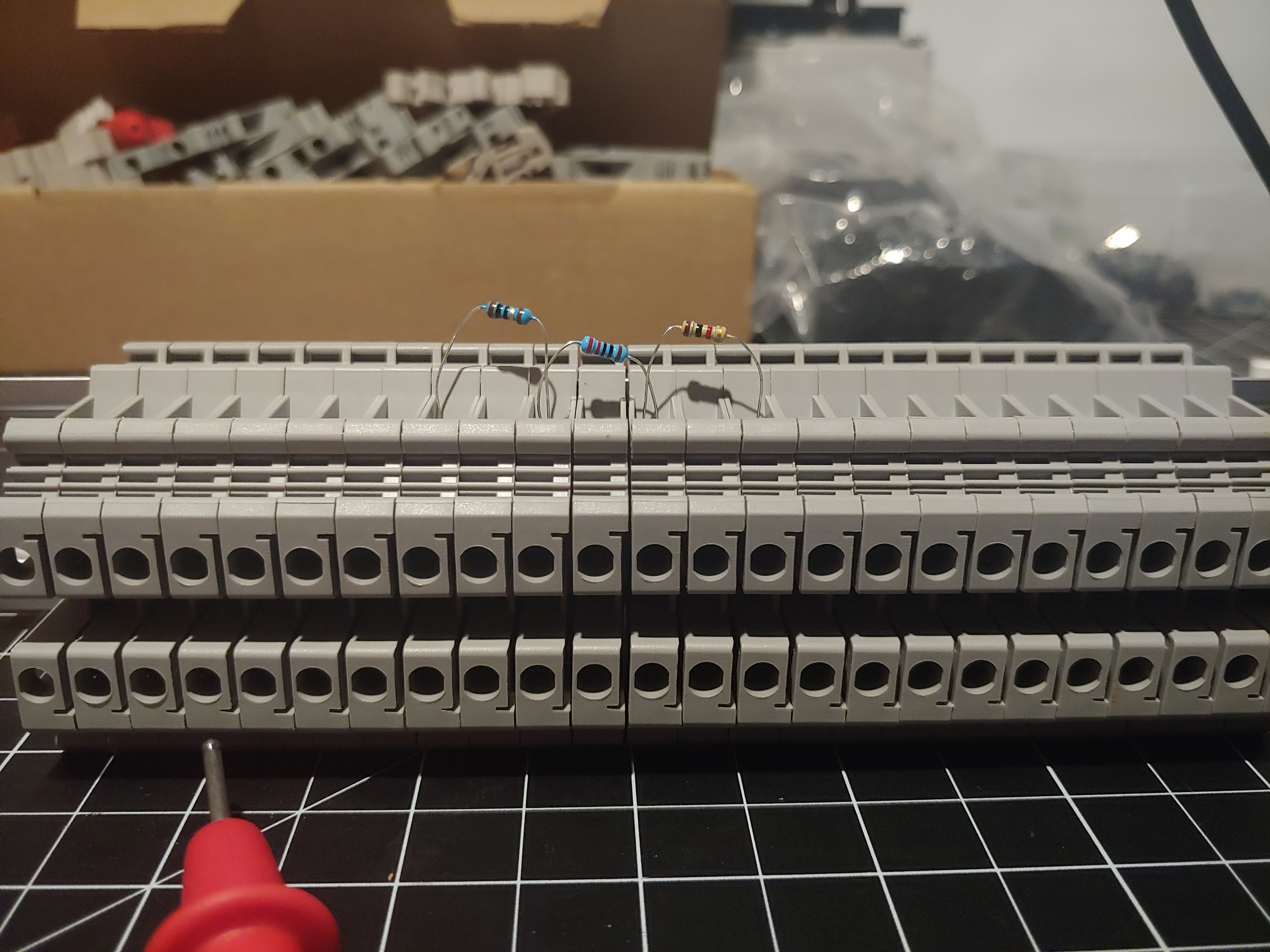
What you’re seeing above is 3 different resistors in series in a strip of terminal blocks. This is equivalent to the following schematic:
Measuring across each resistor in order from left to right:
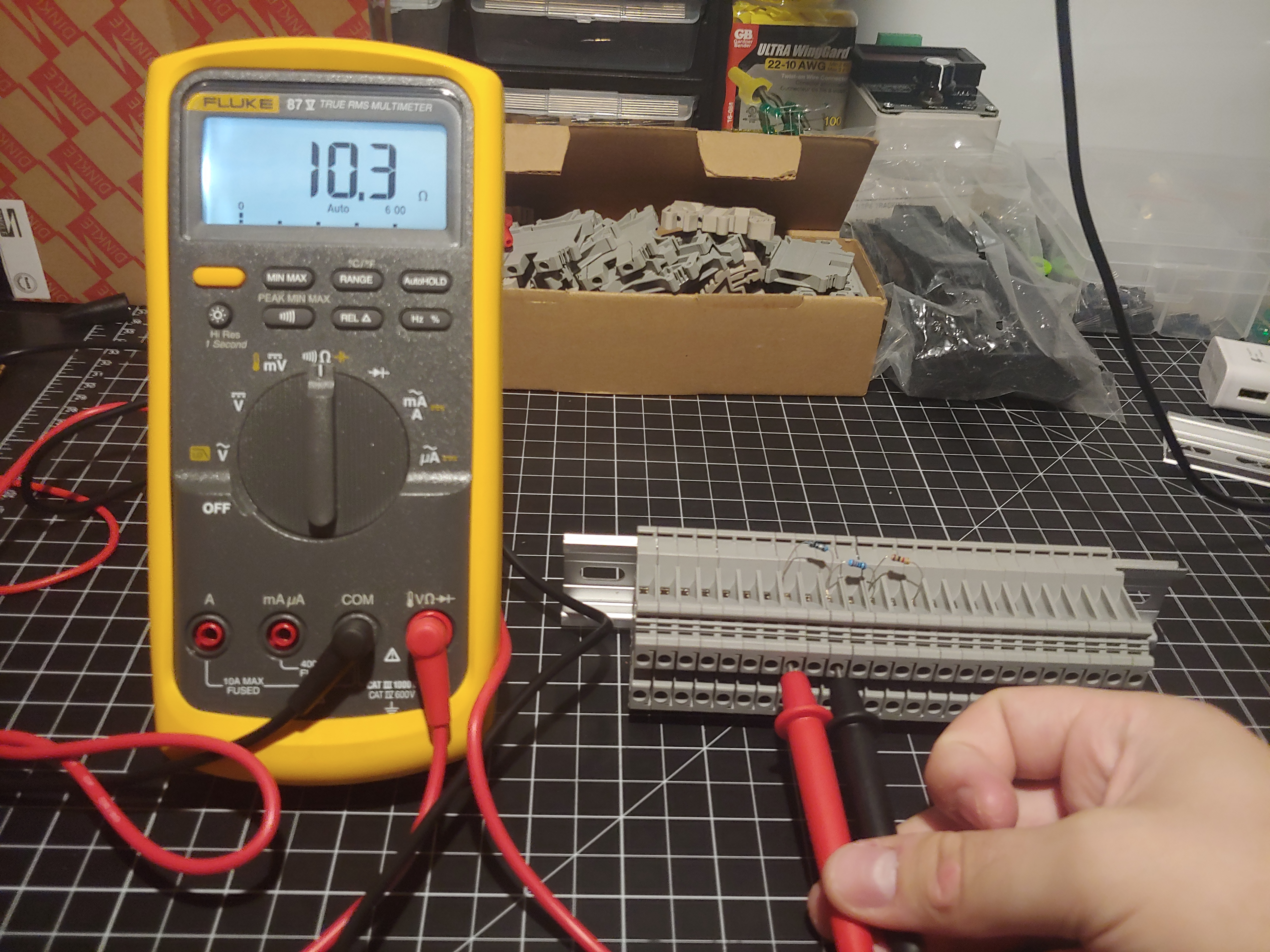
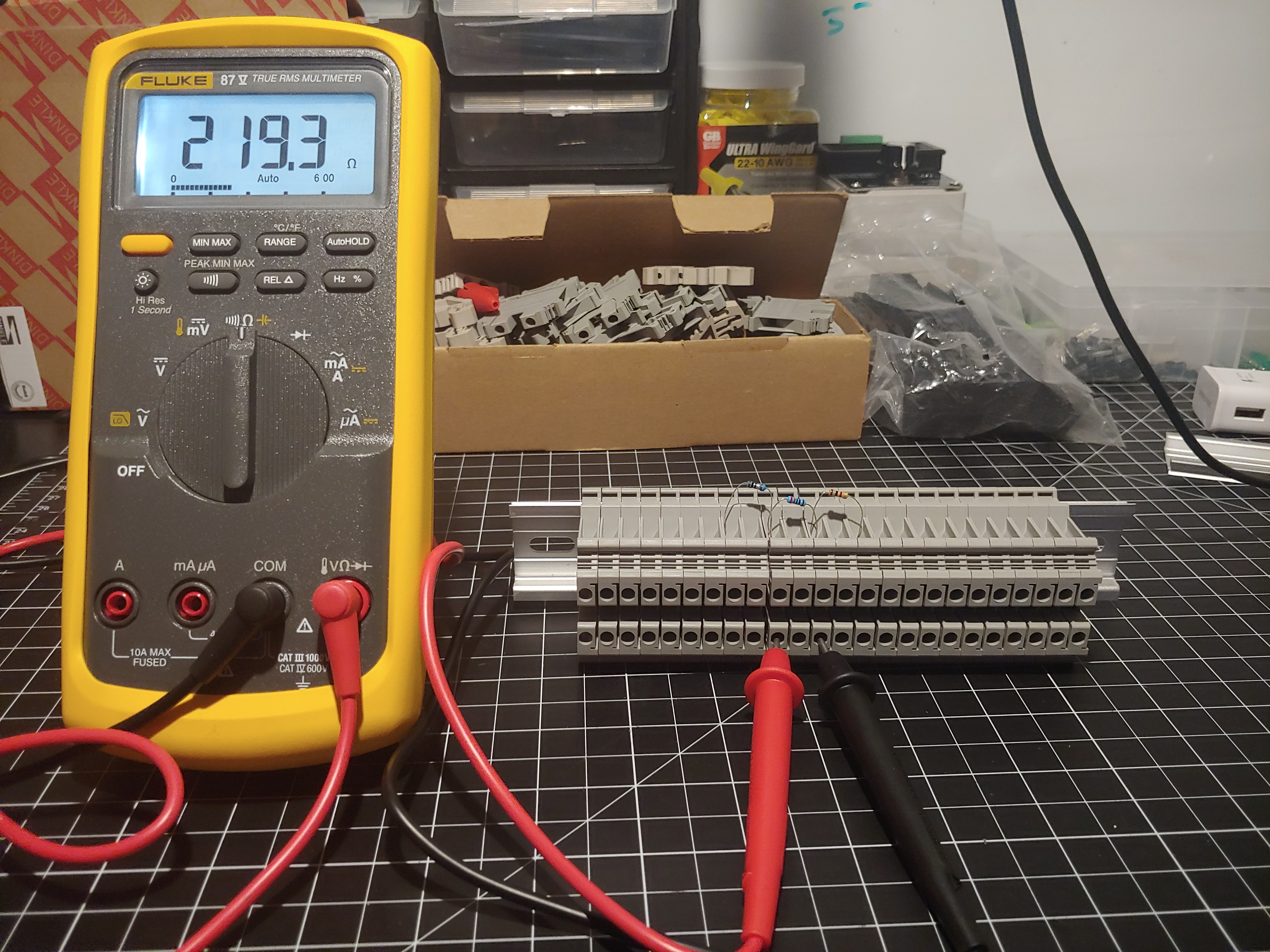
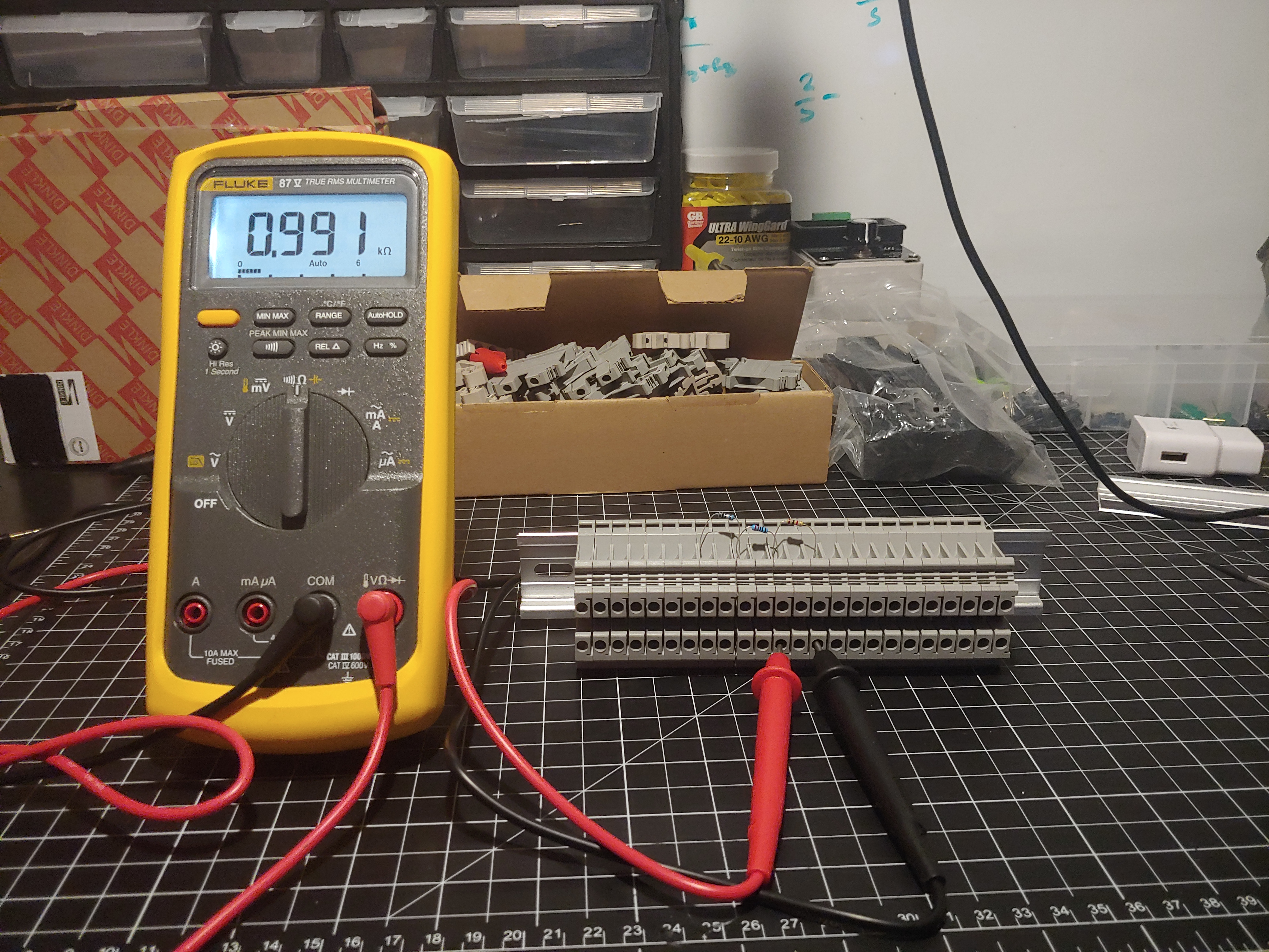
So we have resistor values of \(10.3\Omega\), \(219.3\Omega\), and \(991\Omega\). If our theory is correct, we should get
\[R_{\text{total}} = 10.3\Omega + 219.3\Omega + 991\Omega = 1220.6\Omega\]This turns out to be exactly the case after taking a measurement across all three resistors:
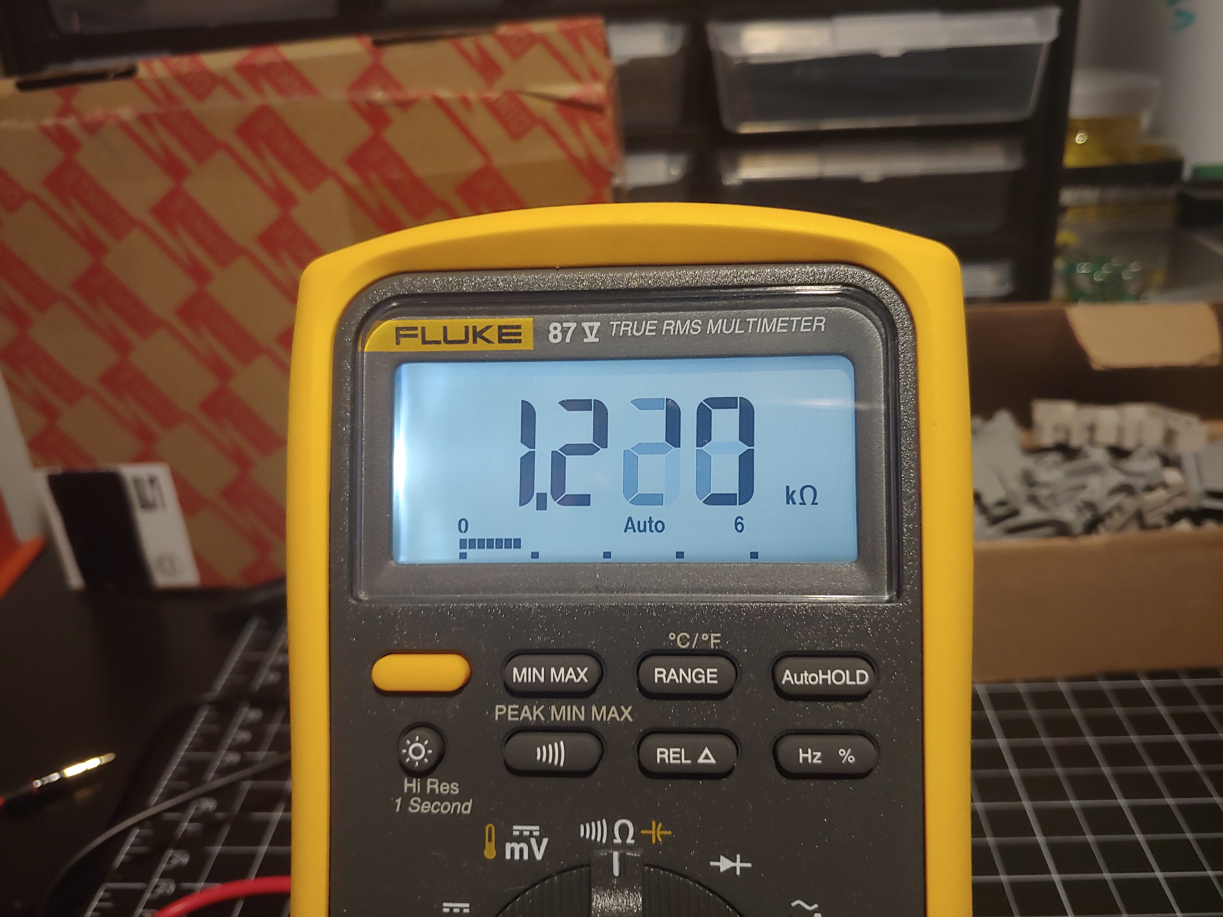
Our theory was less than a percent off, which can be chalked up to environmental factors such as terminal resistance, humidity, and temperature.
The next thing to validate was that the voltage drops across each resistor are proportional to their resistance. We start with a 5v supply, giving us roughly \(3\text{mA}\) of current, which allowing for small deviations is about \(\frac{5\text{V}}{1220.6\Omega} = 4\text{mA}\). Most likely its around \(3.9\text{mA}\) but my power source lacks the precision.
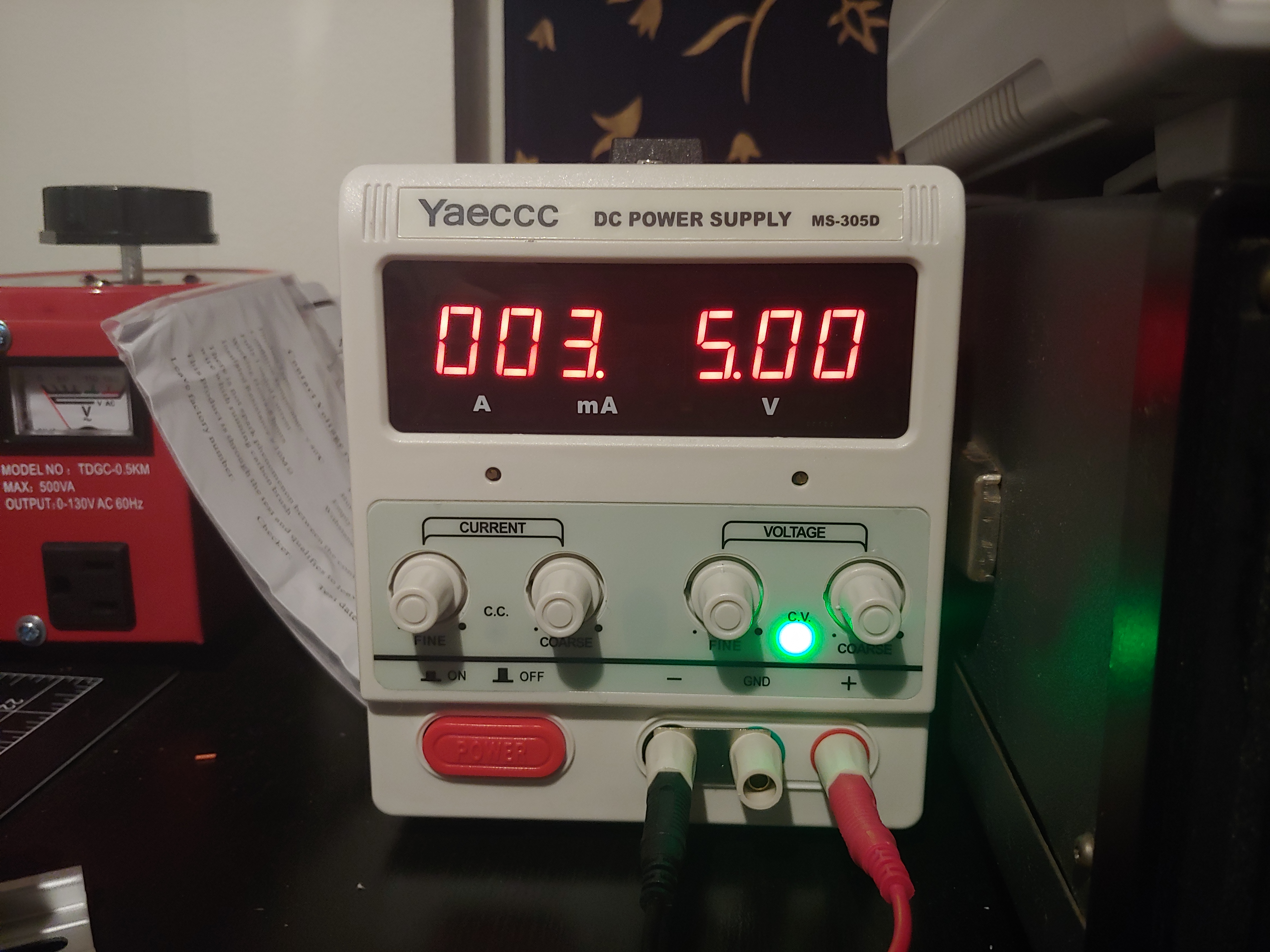
Measuring voltage drops across each resistor in order from left to right:
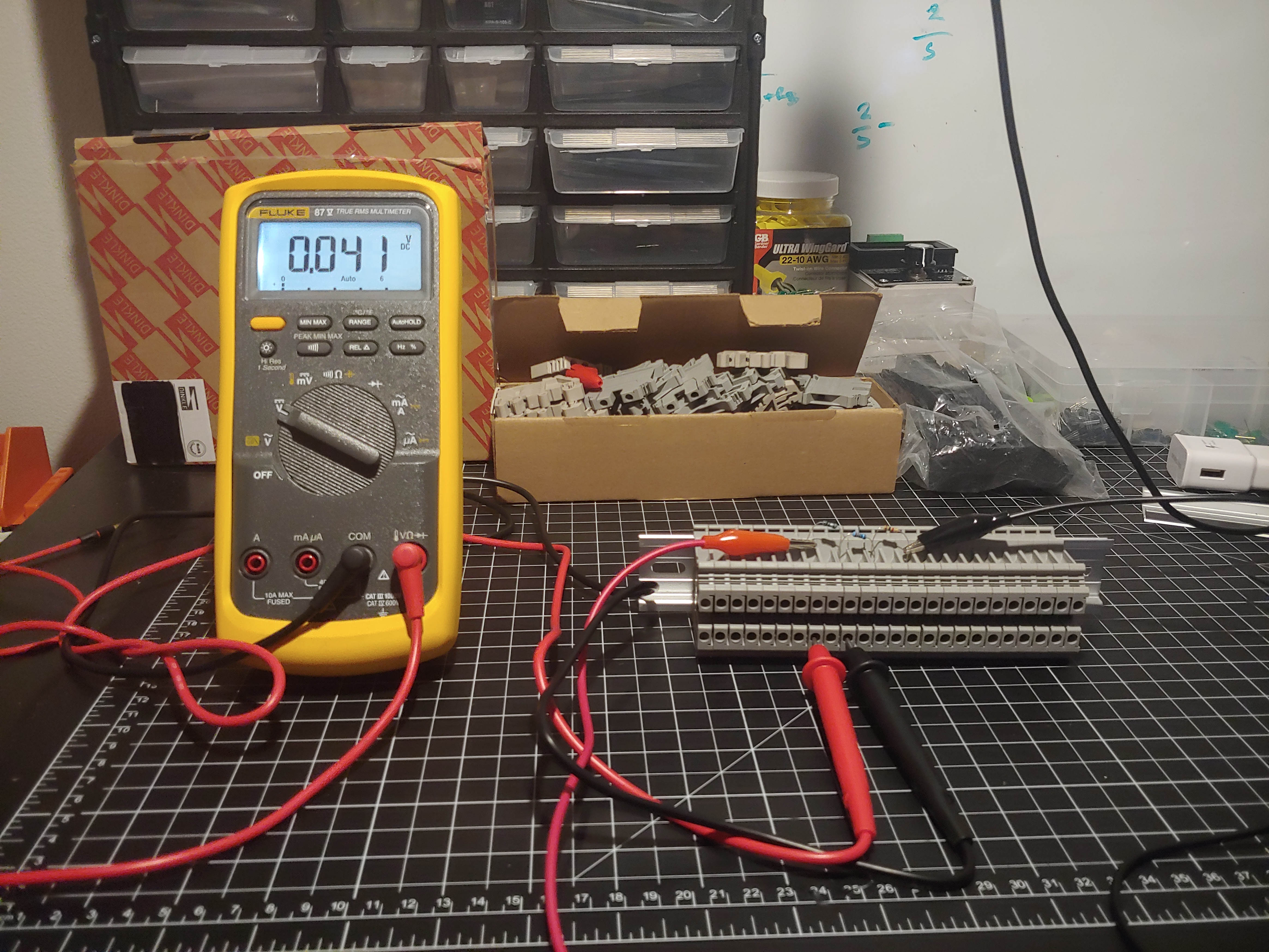 \(4\text{mA} \times 10.3\Omega = 0.0412\text{V}\)
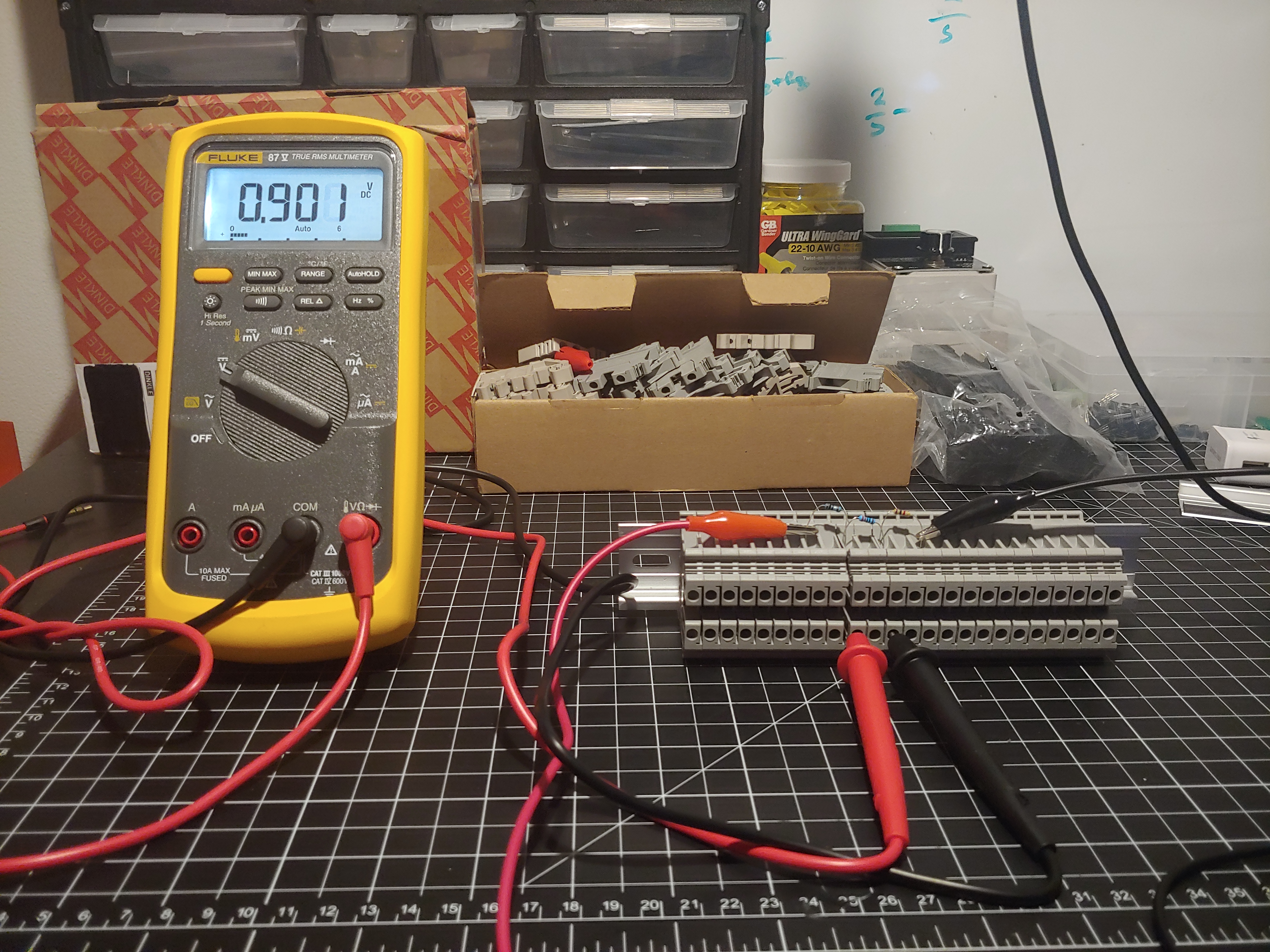 \(4\text{mA} \times 219.3\Omega = 0.8772\text{V}\).
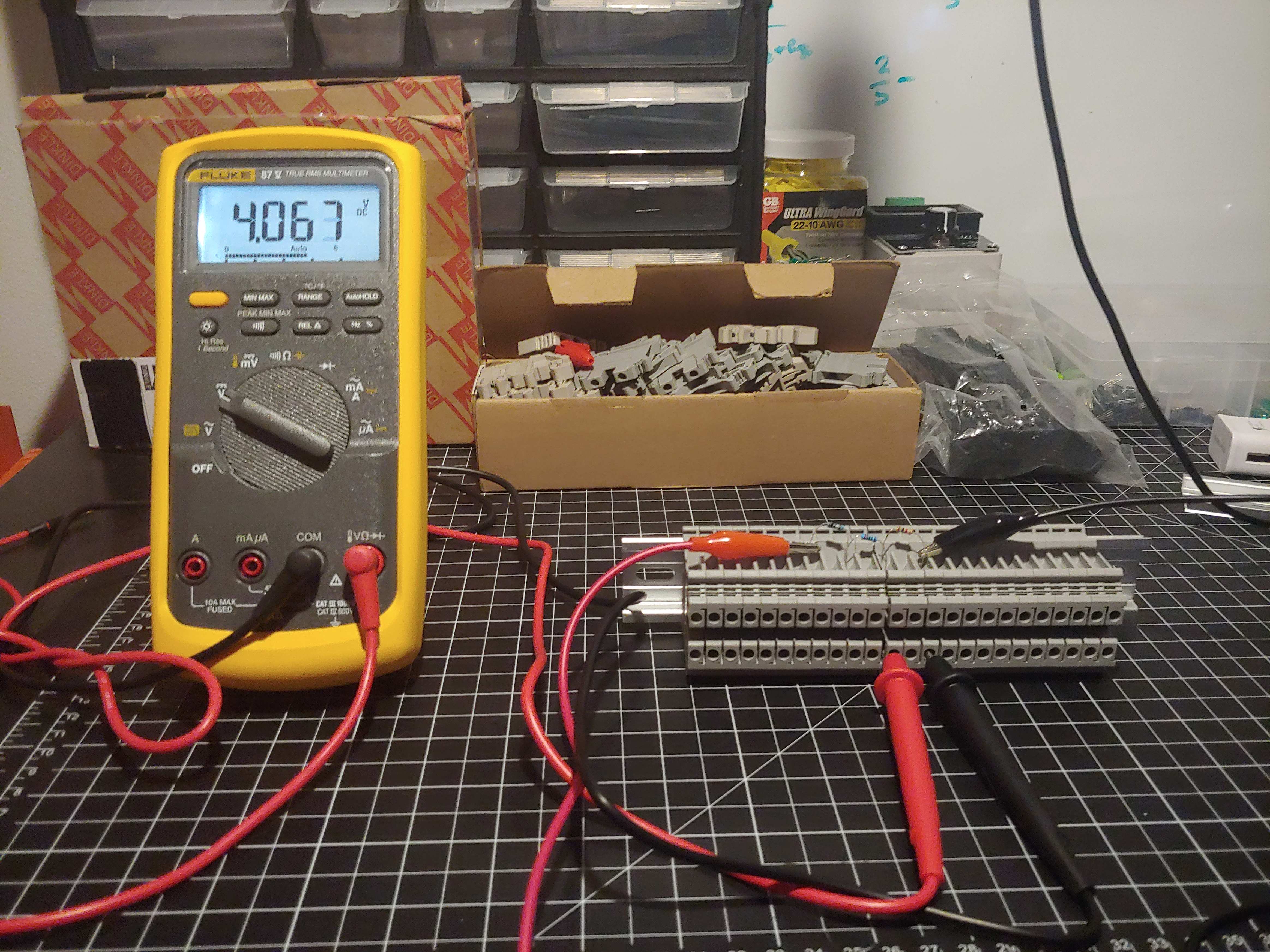 \(4\text{mA} \times 991\Omega = 3.964\text{V}\)
The total of the measurements is
\[\text{V}_{total} = 0.041\text{V} + 0.901\text{V} + 4.067\text{V} = 5.009\text{V}\]And the total of the theoretical drops is
\[\text{V}_{theory} = 0.0412\text{V} + 0.8772\text{V} + 3.964\text{V} = 4.882\text{V}\]Fairly close, what is the total measured drop?
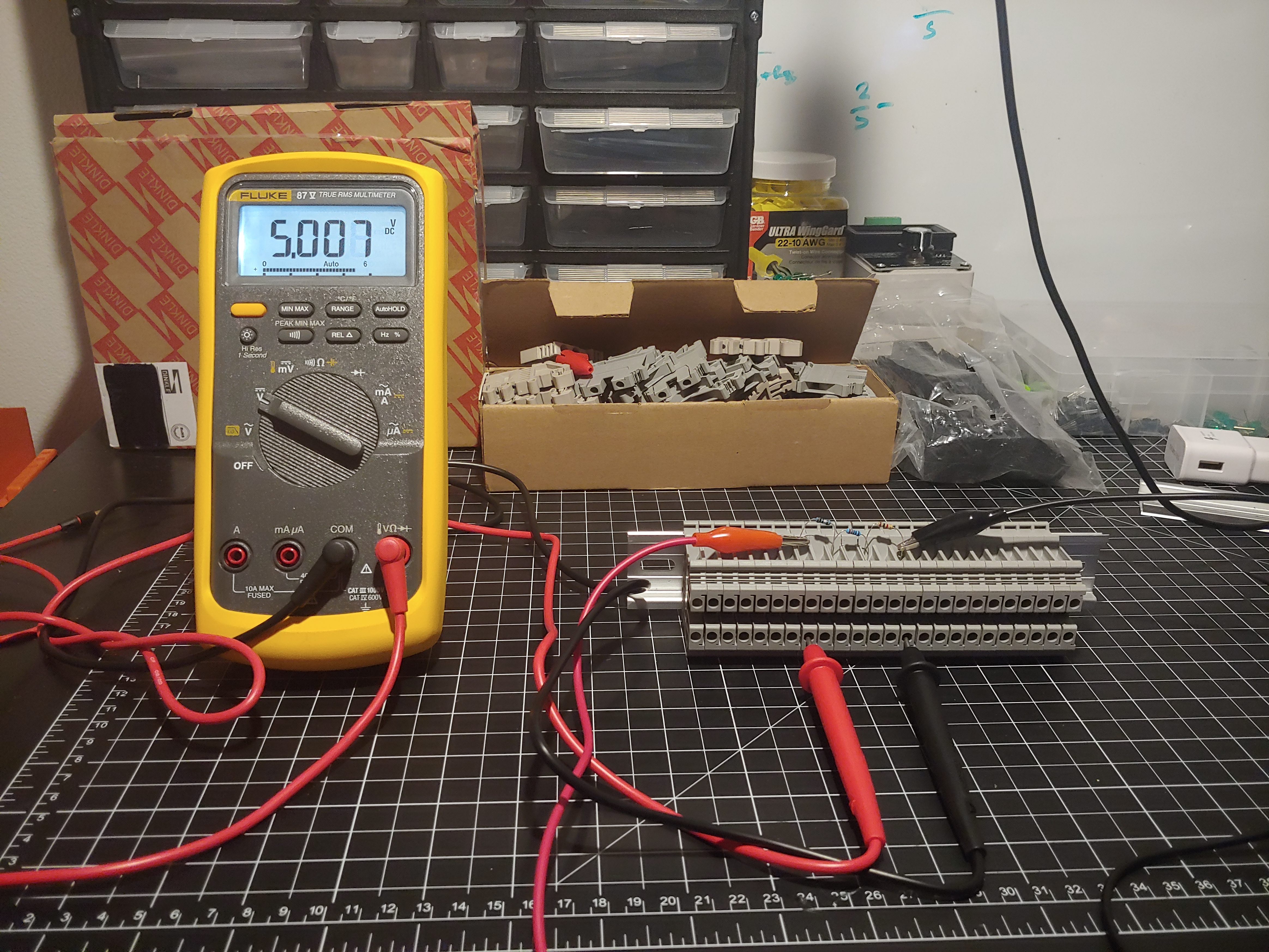
The measured drop is pretty much spot on with the totals of what we measured, and not too far off from the theoretical value calculated from the current and each individual resistance.
Conclusion
This was my first attempt at a lab blog post. I’ll try to keep things simple, but I may also be leaving
important information out. Please don’t hesitate to contact me at automation [at] tkaden [dot] net